All Haynes Digital Online Manuals are currently 50% off. They feature everything you love about our books in an instantly accessible digital online form, that you can use via any device with an internet connection.
This page is taken directly from our digital online manual 24065 for the 1988-98 Chevrolet and GMC C/K 1500/2500/3500 pickup trucks (including 1999-2000 C/K Classics), Chevy Tahoe, Blazer, and Suburban, and GMC Yukon, Yukon Denali, and Suburban, 2WD or 4WD with V6 or V8 gasoline engines, but it applies to many GM vehicles that use 4.3 liter V6, and 5.0 liter, 5.7 liter and other V8 motors. There is no recommended service interval for a water pump, they all eventually wear internally and start leaking or making noise.
Removal
- Disconnect the negative cable from the battery.
- Drain the coolant via the radiator petcock or lower radiator hose.
- Loosen the fan pulley nuts/bolts and then remove the drivebelt.
- Loosen the hose clamps for the lower radiator hose and disconnect the hose from the water pump. On 7.4 liter V8 models, disconnect the coolant by-pass hose from the water pump.
- Remove the fan assembly and water pump pulley.
- (See illustration) On some models the compressor, alternator or power steering brackets attach to the water pump. Where necessary, loosen the components so that the brackets can be moved aside and the water pump bolts removed.
Remove all accessory mounting brackets (arrow) that attach to the water pump bolts or studs.

- (See illustrations) Remove the mounting bolts from the water pump and detach it from the block. It may be necessary to grasp the pump securely and rock it back-and-forth to break the gasket seal.
Remove the four mounting nuts/bolts (arrows) and detach the pump from the engine block.

Grasp the water pump by the pulley mounting flange and rock it back-and-forth to break the gasket seal.

Installation
- Clean the sealing surfaces on both the block and the water pump. Wipe the mating surfaces with a rag saturated with lacquer thinner or acetone.
- Apply a thin layer of RTV sealant to the block mounting surfaces and install new water pump gaskets.
- Apply a thin layer of RTV sealant to the water pump mounting surfaces.
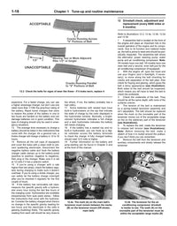
- Place the water pump in position and install the bolts and studs finger-tight. Work carefully so the gaskets don’t slip out of position. Remember to replace any mounting brackets secured by the water pump mounting bolts.
Tighten the bolts to the proper torque:
All engines 30 ft-lbs - Install the water pump pulley and fan assembly and tighten the pulley nuts by hand.
- Install the lower radiator hose, heater hose and hose clamps. Tighten the hose clamps securely.
- Install the drive belt/s and tighten the fan mounting nuts securely.
Fan mounting nuts 18 ft-lbs - Add coolant to the proper level in the radiator and reservoir but don't replace caps.
- Connect the cable to the negative terminal of the battery.
- Start the engine and check the water pump and hoses for leaks. Run the engine outside or in a well ventilated area until it reaches normal operating temperature. Check coolant level and top off if needed.