All Haynes Digital Online Manuals are currently 50% off. They feature everything you love about our books in an instantly accessible digital online form, that you can use via any device with an internet connection.
This page is taken directly from our digital online manual 30042 for the 1994-2008 Dodge Ram 1500, 2500, and 3500 pickup trucks, 2WD or 4WD with gasoline or diesel engines. Every 6 months or 6,000 miles you should check the battery terminals for corrosion, make sure the clamps are tight, and check the cables for cracks, cuts and heat damage. In normal usage the battery should be good for 5 years of use, or more. To be safe, start checking it with a multimeter after 4 years, or every 6 months if you don't know the age. Details on testing a battery are here: How to Test a Car Battery with a Multimeter.
Warning: Hydrogen gas is produced by the battery, so keep open flames and lighted cigarettes away from it at all times. Always wear eye protection when working around a battery. Rinse off spilled electrolyte immediately with large amounts of water.
Caution: Always disconnect the negative cable first and hook it up last or you might accidentally short the battery with the tool that you’re using to loosen the cable clamps.
Battery
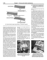
- Disconnect the cable from the negative battery terminal (see illustrations), then disconnect the cable from the positive terminal.
Illustration 3.1a When disconnecting the battery cables, always disconnect the cable from the negative terminal (1) first, then disconnect the cable from the positive terminal (2). After the battery cables are disconnected, remove the battery hold-down bolt (3) and the hold-down clamp (4) - later model shown

Illustration 3.1b On earlier models, there are two hold down bolts and a strap across the top of the battery. However, disconnecting the terminals is the same as above.

- Remove the battery hold-down bolt(s) and hold-down clamp.
- Lift out the battery. Be careful - it’s heavy.
Note: Battery straps are available at most auto parts stores for a reasonable price to make it easier to lift and remove the battery.
- While the battery is out, inspect the area underneath the tray for corrosion. Clean the battery tray, then use a baking soda/water solution to neutralize any deposits to prevent further oxidation. If the metal around the tray is corroded, too, clean it as well and spray the area with a rust-inhibiting paint.
- If corrosion has leaked down past the battery tray, remove the tray for further cleaning.
- If you are replacing the battery, make sure you get one that’s identical, with the same dimensions, amperage rating, cold cranking rating, etc.
- Installation is the reverse of removal.
Battery tray
Left side
- Remove the battery (see Steps 1 through 3 above).
- Detach the wiring harness clips from the battery tray (see illustration).
illustration 3.9 Topside battery tray mounting details - 1) Wiring harness clips 2) Fuse/relay box mounting fasteners 3) Tray mounting bolts 4) ABS controller bolt

- Remove the engine compartment fuse and relay box mounting bolts.
- Slide the fuse and relay box toward the center of the engine compartment to disengage the two locator pins from their respective slots in the front wall of the battery box, then lift up the fuse and relay box.
- Remove the ABS controller mounting bolt, then support the controller with some wire or with a bungee cord.
- Loosen the lug nuts for the left front wheel. Raise the front of the vehicle and place it securely on jackstands. Remove the left front wheel. Remove the left front wheelhouse splash shield (see Chapter 11 of the Haynes manual for details).
- Mark the location of the cruise control servo (if equipped), then remove the servo retaining screws and detach the servo from the battery tray.
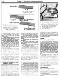
- On models so equipped, remove the three screws that attach the Accelerator Pedal Position Sensor (APPS) assembly to the bottom of the battery tray (see illustration) and detach the APPS assembly from the tray.
Illustration 3.15 Underside battery tray mounting details - 1) APPS mounting screws (Hemi and some diesel models only) 2) Battery temperature sensor 3) Tray mounting bolts

- Unplug the electrical connector from the battery temperature sensor.
- Detach the Evaporative Emissions (EVAP) system purge solenoid from its mounting bracket (see illustration) . It’s not necessary to disconnect the electrical connector from the purge solenoid or to detach the solenoid mounting bracket from the battery tray, which is attached to the underside of the tray by a pair of retaining screws (unless you’re planning to replace the tray).
Illustration 3.17 To detach the EVAP purge solenoid from its mounting bracket, depress this locking tang and slide the solenoid off its bracket

- Disconnect the ground cable from the left front fender.
- Remove the battery tray mounting bolts and remove the battery tray.
- Installation is the reverse of removal.
Right side
- Removal of the right-side battery tray, on models so equipped, is similar to the removal procedure of the left side battery tray, except that the air filter housing must be removed (Full details are in Chapter 4A or Chapter 4B of your Haynes manual), and some of the steps related to left side tray removal will not apply.